Parametric Line-up
Central Bank of Kuwait
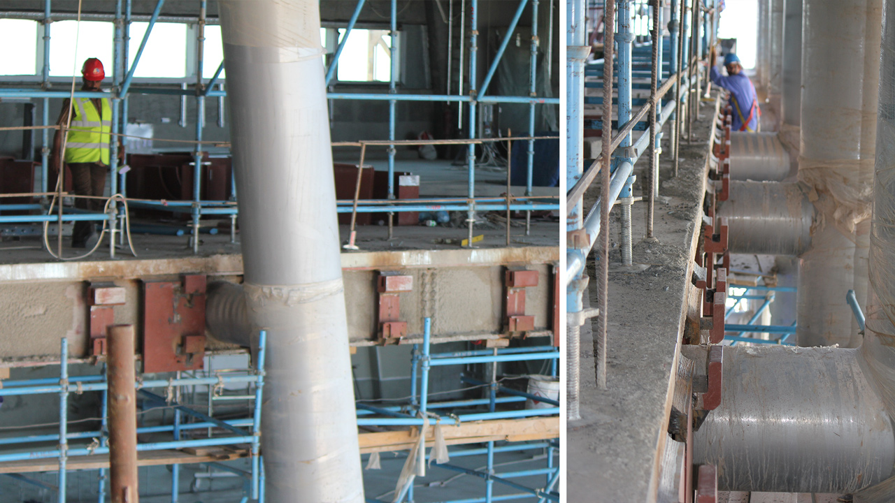
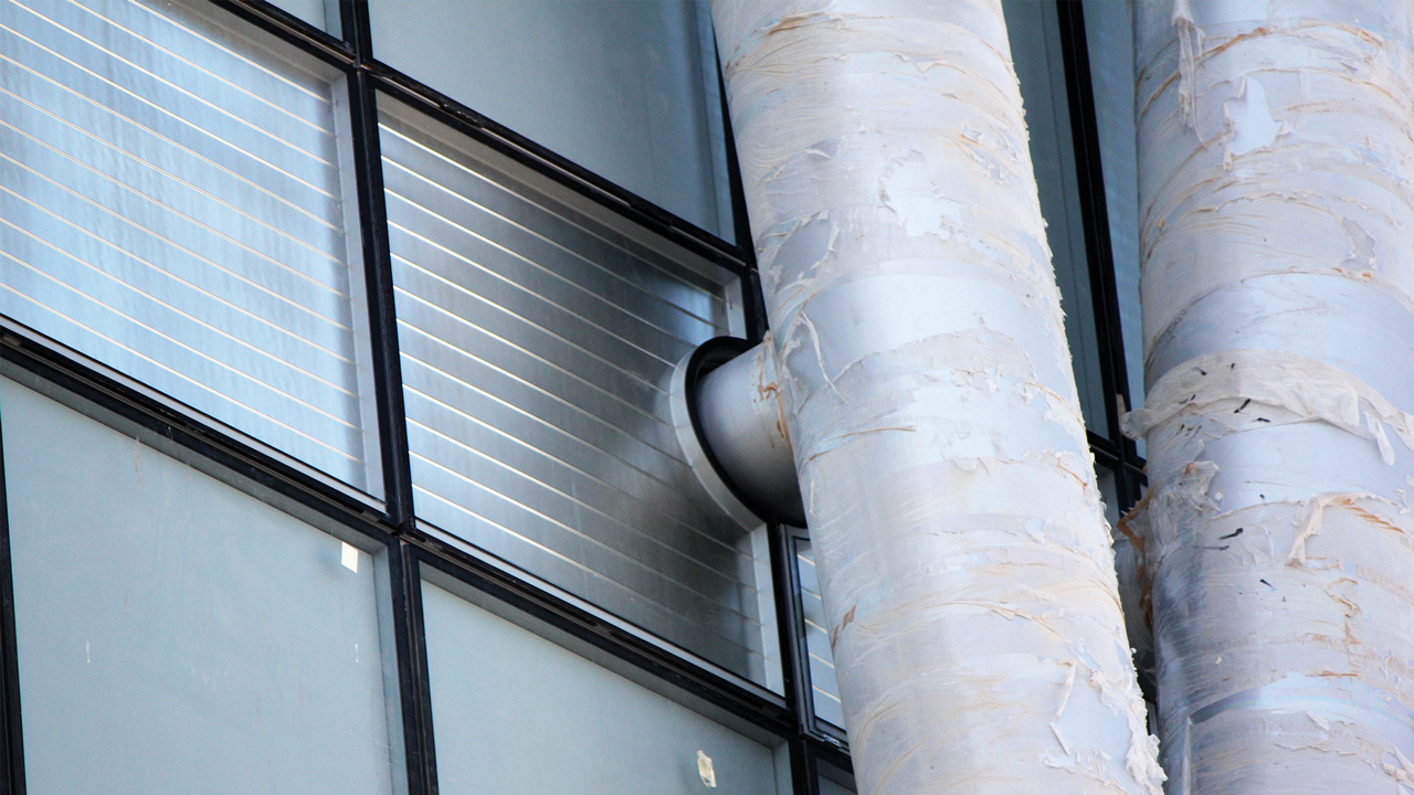
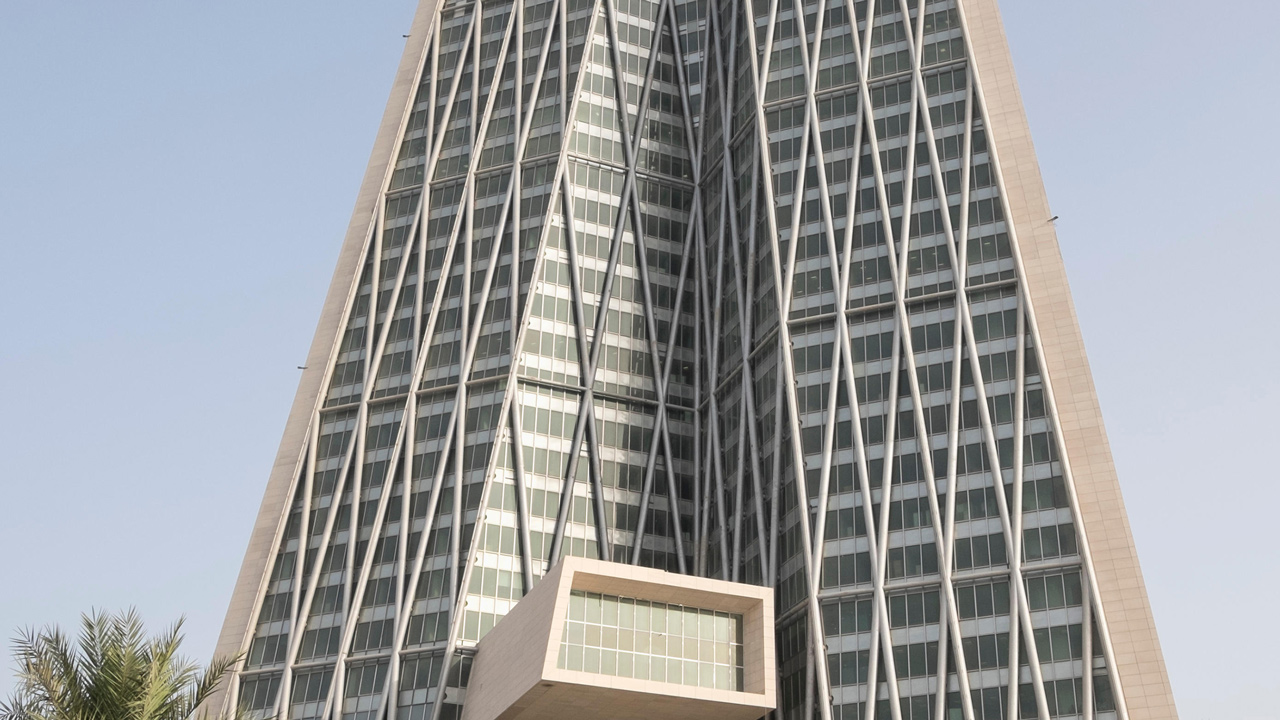
Imagine a building, which is 240 meters high. Its facade is inclined and it has an external, diamond-shaped tubular structure. How many different times is there a gap in facade so that the building and the supporting structure can be joined together?
Exactly: an awful lot of times.
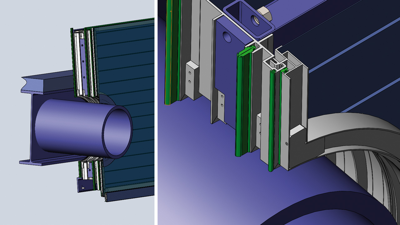
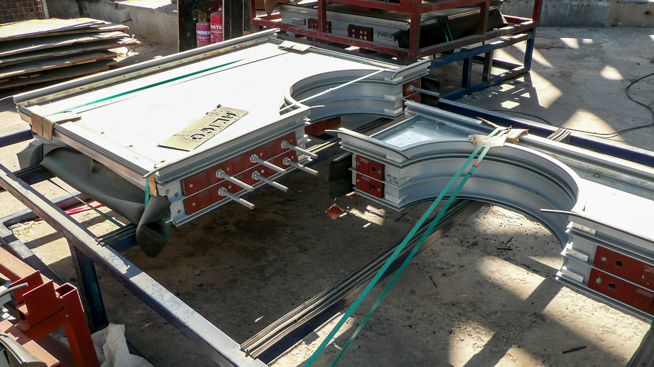
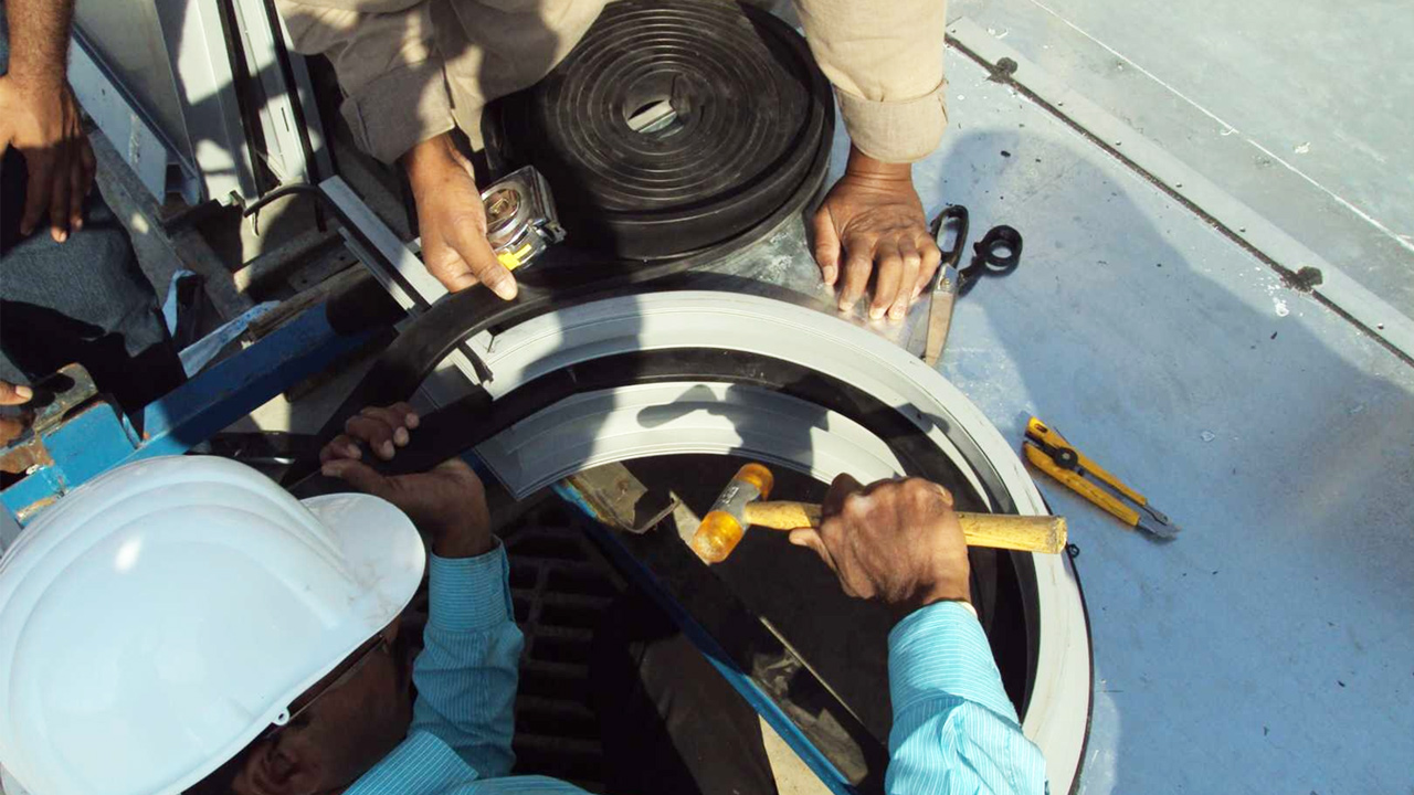
Or even: Each element, where this joint needs to be accommodated, has a different geometry. Even if the differences in some cases are only a few millimeters, all of the connectors are unique.
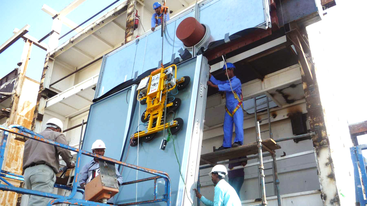
When we first got involved in this project, the task was not just: Work out the geometry for every single location where a joint passes through the facade! Rather, the corresponding facade elements also had to be defined as 3D data sets before they could be manufactured.
Tricky situation
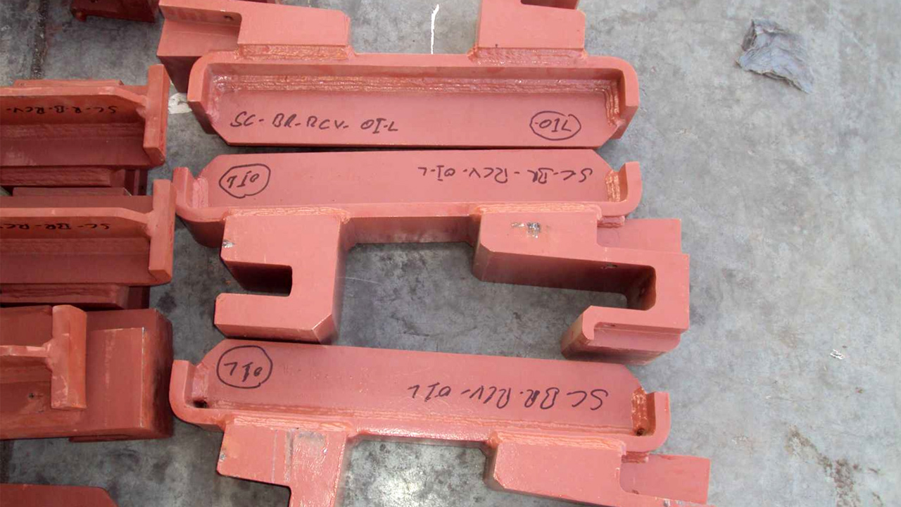
During the planning of the work it had become obvious that the previous approach of depicting the facade construction in 2D would not work on the actual facade. In addition, the now completed shell construction showed greater tolerances than in the original plans. A further complication was that many consoles from which the facade elements were to be suspended had already been produced and had to be used.
Parametric optimization
A completely new set of measurements – in particular of the exact position of the tubular structure in relation to the shell – was required before a valid 3D wire frame could be built, i.e. a digital 3D model of the facade.
Approximately 175,000 measurements had to be taken for this. An exact analysis of all of the points where there was a gap in the facade and other details was only possible on this basis of the actual 3D facade model.
We created almost 90 so-called master models for the 3,700 different elements that were to be used to connect the shell and the tubular structure, and these served as the basic geometric type for 50 to 90 further drawings each.
We forgot to say that the building had to be explosion-resistant up to the tenth floor and bullet-resistant up to the thirtieth floor – but this was still one of the simpler tasks.
